CSR bus
The amaranth_soc.csr.bus module contains primitives to implement and access the registers of peripherals through a bus interface.
Introduction
Overview
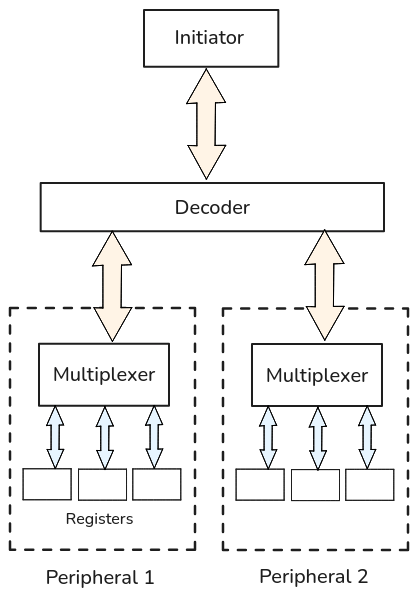
The CSR bus API provides unopinionated primitives for defining and connecting the Control and Status Registers of SoC peripherals, with an emphasis on safety and resource efficiency. It is composed of low-level register interfaces, multiplexers that provide access to the registers of a peripheral, and bus decoders that provide access to subordinate bus interfaces.
This diagram shows a CSR bus decoder being used to provide access to the registers of two peripherals:
Examples
Defining registers
A CSR register is a Component with an Element member in its interface, oriented as input and named "element".
For example, this component is a read/write register with a configurable width:
class MyRegister(wiring.Component):
    def __init__(self, width):
        super().__init__({
            "element": In(csr.Element.Signature(width, "rw")),
            "data": Out(width),
        })

    def elaborate(self, platform):
        m = Module()
        storage = Signal.like(self.data)

        with m.If(self.element.w_stb):
            m.d.sync += storage.eq(self.element.w_data)

        m.d.comb += [
            self.element.r_data.eq(storage),
            self.data.eq(storage),
        ]

        return m
CSR bus transactions go through the Element port and always target the entire register. Transactions are completed in one clock cycle, regardless of the register width. A read and a write access can be part of the same transaction.
Accessing registers
A Multiplexer can provide access to the registers of a peripheral through a CSR bus Interface. Registers must first be added to a MemoryMap, which is used to instantiate the multiplexer.
The following example shows a very basic timer peripheral with an 8-bit CSR bus and two 24-bit registers, Cnt and Rst. The value of Cnt is incremented every clock cycle, and can be reset by a CSR bus write to Rst:
class BasicTimer(wiring.Component):
    class Cnt(wiring.Component):
        element: In(csr.Element.Signature(width=24, access="r"))
        r_stb:   Out(1)
        r_data:  In(unsigned(24))

        def elaborate(self, platform):
            m = Module()
            m.d.comb += [
                self.r_stb.eq(self.element.r_stb),
                self.element.r_data.eq(self.r_data),
            ]
            return m

    class Rst(wiring.Component):
        element: In(csr.Element.Signature(width=24, access="w"))
        w_stb:   Out(1)
        w_data:  Out(unsigned(24))

        def elaborate(self, platform):
            m = Module()
            m.d.comb += [
                self.w_stb.eq(self.element.w_stb),
                self.w_data.eq(self.element.w_data),
            ]
            return m

    def __init__(self):
        super().__init__({
            "csr_bus": In(csr.Signature(addr_width=3, data_width=8)),
        })

        self._reg_cnt = self.Cnt()
        self._reg_rst = self.Rst()

        self.csr_bus.memory_map = MemoryMap(addr_width=3, data_width=8, alignment=2)
        self.csr_bus.memory_map.add_resource(self._reg_cnt, size=3, name=("cnt",))
        self.csr_bus.memory_map.add_resource(self._reg_rst, size=3, name=("rst",))

        self._csr_mux = csr.Multiplexer(self.csr_bus.memory_map)

    def elaborate(self, platform):
        m = Module()
        m.submodules.reg_cnt = self._reg_cnt
        m.submodules.reg_rst = self._reg_rst
        m.submodules.csr_mux = self._csr_mux

        connect(m, flipped(self.csr_bus), self._csr_mux.bus)

        count = Signal(unsigned(24))

        m.d.comb += self._reg_cnt.r_data.eq(count)

        with m.If(self._reg_rst.w_stb):
            m.d.sync += count.eq(self._reg_rst.w_data)
        with m.Else():
            m.d.sync += count.eq(count + 1)

        return m
>>> timer = BasicTimer()
>>> for res_info in timer.csr_bus.memory_map.all_resources():
...     print(res_info)
ResourceInfo(path=(Name('cnt'),), start=0x0, end=0x4, width=8)
ResourceInfo(path=(Name('rst'),), start=0x4, end=0x8, width=8)
Registers are always accessed atomically, regardless of their size. Each register is split into chunks according to the CSR bus data width, and each chunk is assigned a consecutive address on the bus.
In this example, the sizes of Cnt and Rst are extended from 24 to 32 bits, because they were added to csr_bus.memory_map with an alignment of 32 bits.
The following diagram shows a read transaction from the Cnt register:
![{'head': {'tick': 0}, 'signal': [{'name': 'clk', 'wave': 'p......'}, {'node': '.AB...C'}, ['csr_bus', {'name': 'addr', 'wave': 'x====x.', 'data': [0, 1, 2, 3]}, {'name': 'r_stb', 'wave': '01...0.'}, {'name': 'r_data', 'wave': '0.45670', 'node': '..1234.', 'data': ['0x01', '0x00', '0xa5', '0x00']}], {}, ['csr_mux', {'name': 'r_shadow', 'wave': 'x.3...x', 'node': '..b....', 'data': ['0xa50001']}], {}, ['reg_cnt', {'name': 'r_stb', 'wave': '010....'}, {'name': 'r_data', 'wave': '=3=====', 'node': '.a.....', 'data': ['0xa50000', '0xa50001', '0xa50002', '0xa50003', '0xa50004', '0xa50005', '0xa50006']}]], 'edge': ['A+B t1', 'a-~>b', 'B+C t2', 'b~>1'], 'config': {'hscale': 2, 'skin': 'default'}}](_images/csr/bus/example_mux_read.svg)
The Multiplexer adds a delay of 1 clock cycle to CSR bus reads (represented by t1) between the time of assertion of csr_bus.r_stb and the time the first chunk is transmitted to csr_bus.r_data.
A read transaction targeting Cnt requires 4 bus reads to complete and has a latency of 4 clock cycles (represented by t2).
When the first chunk of Cnt is read, the value of all of its chunks (at point labelled a) is captured by a shadow register internal to the multiplexer (at point labelled b). Reads from any chunk return the captured values (at points labelled 1, 2, 3, 4).
The following diagram shows a write transaction to the Rst register, which resets the value of the Cnt register as a side-effect:
![{'head': {'tick': 0}, 'signal': [{'name': 'clk', 'wave': 'p......'}, {'node': '.A...BC'}, ['csr_bus', {'name': 'addr', 'wave': 'x====x.', 'data': [4, 5, 6, 7]}, {'name': 'w_stb', 'wave': '01...0.'}, {'name': 'w_data', 'wave': 'x4567x.', 'node': '.1234..', 'data': ['0x44', '0x55', '0x66', '0x00']}], {}, ['csr_mux', {'name': 'w_shadow', 'wave': 'x.===3x', 'node': '..a..b', 'data': ['0x000044', '0x005544', '0x665544', '0x665544']}], {}, ['reg_rst', {'name': 'w_stb', 'wave': '0....10'}, {'name': 'w_data', 'wave': 'x....3x', 'node': '.....c.', 'data': ['0x665544']}], {}, ['reg_cnt', {'name': 'r_data', 'wave': '======3', 'node': '......d', 'data': ['0xa50007', '0xa50008', '0xa50009', '0xa5000a', '0xa5000b', '0xa5000c', '0x665544']}], {}], 'edge': ['A+B t1', '1~->a', 'B+C t2', 'b~->c', 'c~->d'], 'config': {'hscale': 2, 'skin': 'default'}}](_images/csr/bus/example_mux_write.svg)
A write transaction targeting Rst requires 4 bus writes to complete and has a latency of 4 clock cycles (represented by t1).
When a chunk of Rst is written (at point labelled 1), the written value is captured by a shadow register internal to the multiplexer (at point labelled a). A write to the last chunk (at point labelled 4) causes all captured values to be written to the register (at point labelled c).
The Multiplexer adds a delay of 1 clock cycle to CSR bus writes (represented by t2) between the time of assertion of csr_bus.w_stb and the time of assertion of reg_rst.w_stb.
As a side-effect of the transaction, the next value of Cnt becomes the value that was written to Rst (at point labelled d).
Warning
To safely access registers over the bus interface of a Multiplexer, the following
rules apply:
the bus initiator must have exclusive ownership over the address range of the multiplexer until the register transaction is either completed or aborted.
the bus initiator must access a register in ascending order of addresses, but it may abort the transaction after any bus cycle.
Accessing a hierarchy of registers
A Decoder can provide access to group of Multiplexers and subordinate Decoders, forming a hierarchical address space of CSR registers.
In the following example, a CSR decoder provides access to the registers of two peripherals:
timer0 = BasicTimer()
timer1 = BasicTimer()

csr_dec = csr.Decoder(addr_width=16, data_width=8)
csr_dec.add(timer0.csr_bus, addr=0x0000, name="timer0")
csr_dec.add(timer1.csr_bus, addr=0x1000, name="timer1")
>>> for res_info in csr_dec.bus.memory_map.all_resources():
...     print(res_info)
ResourceInfo(path=(Name('timer0'), Name('cnt')), start=0x0, end=0x4, width=8)
ResourceInfo(path=(Name('timer0'), Name('rst')), start=0x4, end=0x8, width=8)
ResourceInfo(path=(Name('timer1'), Name('cnt')), start=0x1000, end=0x1004, width=8)
ResourceInfo(path=(Name('timer1'), Name('rst')), start=0x1004, end=0x1008, width=8)
Although there is no functional difference between adding a group of registers directly to a Multiplexer and adding them to multiple Multiplexers that are aggregated with a Decoder, hierarchical CSR buses are useful for organizing a hierarchical design.
If many peripherals are directly served by a single Multiplexer, a very large amount of ports will connect the peripheral registers to the multiplexer, and the cost of decoding logic would not be attributed to specific peripherals. With a Decoder, only five signals per peripheral will be used, and the logic could be kept together with the peripheral.
Register interfaces
- class Element.Access
Register access mode.
Coarse access mode for the entire register. Individual fields can have more restrictive access mode, e.g. R/O fields can be a part of an R/W register.
- R = 'r'
Read-only mode.
- W = 'w'
Write-only mode.
- RW = 'rw'
Read/write mode.
- class Element.Signature
CSR register signature.
- Parameters:
width (
int) – Width of the register.access (
Element.Access) – Register access mode.
- Members:
r_data (
In(width)) – Read data. Must be always valid, and is sampled whenr_stbis asserted.r_stb (
Out(1)) – Read strobe. Registers with read side effects should perform the read side effect when this strobe is asserted.w_data (
Out(width)) – Write data. Valid only whenw_stbis asserted.w_stb (
Out(1)) – Write strobe. Registers should update their value or perform the write side effect when this strobe is asserted.
- create(*, path=None, src_loc_at=0)
Create a compatible interface.
See
amaranth.lib.wiring.Signature.create()for details.- Return type:
- __eq__(other)
Compare signatures.
Two signatures are equal if they have the same width and register access mode.
- class amaranth_soc.csr.bus.Element
CSR register interface.
A low-level interface to a single atomically readable and writable register in a peripheral. This interface supports any register width and semantics, provided that both reads and writes always succeed and complete in one cycle.
- Parameters:
width (
int) – Width of the register.access (
Element.Access) – Register access mode.path (iterable of
str) – Path to this interface. Optional. Seeamaranth.lib.wiring.PureInterface.
Bus interfaces
- class amaranth_soc.csr.bus.Signature
CSR bus signature.
- Parameters:
- Members:
addr (
Out(addr_width)) – Address for reads and writes.r_data (
In(data_width)) – Read data. Valid on the next cycle afterr_stbis asserted. Otherwise, zero. (Keeping read data of an unused interface at zero simplifies multiplexers.)r_stb (
Out(1)) – Read strobe. Ifaddrpoints to the first chunk of a register, captures register value and causes read side effects to be performed (if any). Ifaddrpoints to any chunk of a register, latches the captured value tor_data. Otherwise, latches zero tor_data.w_data (
Out(data_width)) – Write data. Must be valid whenw_stbis asserted.w_stb (
Out(1)) – Write strobe. Ifaddrpoints to the last chunk of a register, writes captured value to the register and causes write side effects to be performed (if any). Ifaddrpoints to any chunk of a register, latchesw_datato the captured value. Otherwise, does nothing.
- create(*, path=None, src_loc_at=0)
Create a compatible interface.
See
amaranth.lib.wiring.Signature.create()for details.- Return type:
- __eq__(other)
Compare signatures.
Two signatures are equal if they have the same address width and data width.
- class amaranth_soc.csr.bus.Interface
CSR bus interface.
A low-level interface to a set of atomically readable and writable peripheral CSR registers.
- Parameters:
- memory_map
Memory map of the bus.
- Return type:
MemoryMaporNone- Raises:
ValueError – If set to a memory map that does not have the same address and data widths as the bus interface.
Bus primitives
- class amaranth_soc.csr.bus.Multiplexer
CSR register multiplexer.
An address-based multiplexer for CSR registers implementing atomic updates.
Writes are registered, and are performed 1 cycle after
w_stbis asserted.Note
Because the CSR bus conserves logic and routing resources, it is common to e.g. bridge a CSR bus with a narrow N-bit datapath to a CPU with a wider W-bit datapath (W>N) in cases where CSR access latency is less important than resource usage.
In this case, two strategies are possible for connecting the CSR bus to the CPU:
The CPU could access the CSR bus directly (with no intervening logic other than simple translation of control signals). The register alignment should be set to 1 (i.e.
memory_map.alignmentshould be 0), and each R-bit register would occupy ceil(R/N) addresses from the CPU perspective, requiring the same amount of memory instructions to access.The CPU could access the CSR bus through a width down-converter, which would issue W/N CSR accesses for each CPU access. The register alignment should be set to W/N, and each R-bit register would occupy ceil(R/K) addresses from the CPU perspective, requiring the same amount of memory instructions to access.
If the register alignment is greater than 1, it affects which CSR bus write is considered a write to the last register chunk. For example, if a 24-bit register is accessed through an 8-bit CSR bus and a CPU with a 32-bit datapath, a write to this register requires 4 CSR bus writes to complete, and the last write is the one that actually writes the value to the register. This allows determining write latency solely from the amount of addresses occupied by the register in the CPU address space, and the CSR bus data width.
- Parameters:
- Members:
bus (
In(csr.Signature(memory_map.addr_width, memory_map.data_width))) – CSR bus providing access to registers.
- class amaranth_soc.csr.bus.Decoder
CSR bus decoder.
An address decoder for subordinate CSR buses.
- Parameters:
- Members:
bus (
In(csr.Signature(addr_width, data_width))) – CSR bus providing access to subordinate buses.
- align_to(alignment)
Align the implicit address of the next window.
See
align_to()for details.- Returns:
Implicit next address.
- Return type:
- add(sub_bus, *, name=None, addr=None)
Add a window to a subordinate bus.
See
add_window()for details.